


VESKO-T (thermal-oil)

Description
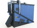
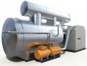
The boiler is a self-supporting, wholly welded cabinet construction. It serves to combust bio-mass on an overfeed stoker above which a suitably shaped vault gathers countercurrent-wise the layout of the waste gases. This process helps to shorten the time for drying fuel. The bottom part of the boiler is made up of a furnace with a displaceable sloping grate. The grate is governed by a hydraulic mechanism and is cooled by the zonated primary air. On the boiler there is the main oil exchanger. The boiler is furnished with heat insulation covered with steel plate with a plastic surface.

Purpose:
Thermo-oil boilers are mainly designed as the heat source of the primary circuit of an ORC. The boiler can also be used for industrial concerns with specialized technological production
- Thermal output 1 – 10 MW
- Working overpressure 0,3 až 1,0 MPa
- Working oil temperatur 250 až 300 °C
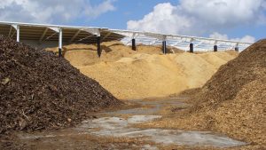
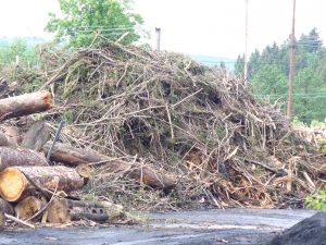
Types of fuel
Fuel
The construction of the combustion chamber along with the use of fuel transport by hydraulic feeders enables to burn even less
quality wood material produced during the wood processing in sawmills, lumbering or cultivating operations in the forests. It is about wood chips, sawdust, bark, shavings, pieces of timber from the saw, peat etc.
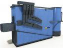
Transport of the fuel
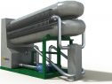
The fuel is transported to the boiler by a hydraulic charging press. Furthermore, it is push through a heated tunnel (the heating of the
heating water), where there is a fuel pre-drying before entering the combustion grate.
Advantages of the concept
The Self-cleaning Abilities of the Boiler:
- The grating inclination, the shape of the ceramic vault and the thrust to the ash container without needing to break slag allows the combustion of very fusible material
- A large extension grate chamber with the correctly inclined vault removes the significant likelihood of flying flue ash
- The cooling of waste gases in the extension grate chamber at a lower temperature than that of the melting of flue ash prevents the clinkering of flue ash in the heating tubes of the spiral exchanger.
Large through-flow capacity of the boiler
- A complex system of feeders having a lineal reversible motion causing by hydraulic cylinders forms the transport routes of the fuel.
- The complete route has large through-flow capacity (minimum cross-section 1200 x 280 mm)
- The transport route is not inclined to blockage (screw feeders or turnstiles, for example, are not able to transport uncrushed bark, and they are inclined to become blocked through the influence of the chords of uncrushed bark).
- The transport routes are able to transport even a large percentage of non-combustible admixtures (rocks, pieces of steel etc.).
Ash Removal:
- Grate ash falls into a container which is a special mechanism connected directly to the boiler and creates a single space with the boiler
- There is no closing element which could lower the through-flow capacity of the ash
- Ash removal can be carried out by an automatic raking transporter to a larger container, such as 10 m3
Perfect automation of the boiler:
- The combustion has been perfected on the basis of under-pressure in the combustion chamber and through a surplus of oxygen in the combustion products.
- The fuel feed and the movement on the grate is regulated in accordance with the fuel?s characteristics.
- All measured quantities, interventions of the safety equipment and defects are transmitted to the dispatching system.